A popping flame is not always a minor torch fault: a backfire can develop into a flashback that travels through the torch, hose and gas system. By the end, you will know how to identify the warning signs, distinguish the two protective functions, install the device correctly and match a Harris unit to your gas equipment.
Key takeaways
- Treat a flashback as flame travel through the torch, hose or gas line.
- Fit a flashback arrestor on both oxygen and fuel-gas lines.
- Use the arrestor’s gas type, pressure and flow ratings to match the nameplate.
- Purge hoses, set pressures correctly and stop work after repeated backfires.
Backfire or flashback: what is happening in the torch?
A backfire is a brief event at the torch tip: you hear a sharp popping flame, the flame may go out, and normal burning returns when gas flow stabilises. A flashback is more serious; the flame travels back through the tip and torch, potentially into the hose, regulator or gas line.
Treat these signs as evidence of a possible flashback rather than harmless noise:
- A repeated popping flame after ignition
- A squealing flame or sudden flame disappearance
- Hose vibration, banging or unusual movement
- The torch, hose connection or arrestor becoming abnormally hot
- A change in the sound that suggests the flame has moved inside the torch
Faults that disturb the correct gas mixture or flow can trigger either event. Check for a blocked or overheated tip, dirty orifices, the wrong tip fitted to the torch, incorrect regulator pressure, poor gas flow, leaking connections, kinked hoses and damaged torch valves.
Repeated backfire points to an unresolved fault; continuing to work can turn it into flashback.
Shut off the gases if you suspect flame travel, then isolate the flashback arrestor and inspect or replace it according to its instructions. A normal exterior and continuing gas flow do not prove that its flame-arresting element, check valve or thermal shutoff survived the heat.
Why a non-return valve alone is not enough
A non-return valve can stop gas moving in the wrong direction; it cannot stop a flame that has already entered the hose, regulator or torch. That is why a check valve alone does not provide flashback protection. Reverse gas flow and flame travel are separate hazards.
A flashback arrestor provides protection through distinct functions:
- The non-return valve blocks oxygen from flowing into the fuel-gas line, or fuel gas from flowing into the oxygen line. It reduces gas mixing upstream, but it does not extinguish an established flame.
- The flame-arresting element quenches the flame front as it reaches the arrestor. Its heat-absorbing passages cool the flame below the temperature needed for propagation, stopping the flashback from continuing through the line.
- The thermal shutoff closes the gas passage when heat from a sustained flashback reaches the device. It is a backup barrier, not a cure for a blocked tip, wrong pressure or damaged torch.
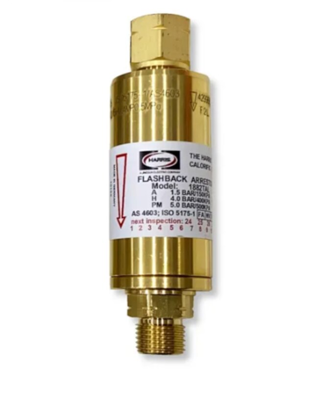
Confirm the functions on the specified Harris model. Do not assume every device sold as a flashback arrestor includes a thermal shutoff or pressure-sensitive shutoff.
After a suspected flashback, isolate the arrestor and follow its instructions for inspection or replacement. A normal-looking casing and continued gas flow do not prove that the flame-arresting element, check valve or thermal shutoff survived the heat. Installing a replacement backward, or on the wrong gas service, can defeat the protection.
Where to fit arrestors on oxygen and fuel-gas lines
Install a separate flashback arrestor in each gas line: one for oxygen and one for fuel gas. Place each device at the regulator outlet or at the torch inlet, depending on the hose layout and the arrestor manufacturer’s instructions. A torch-side arrestor is not automatically equivalent to protection at a regulator or manifold.
For a long hose run, exposed manifold, or higher-risk arrangement, the design may require protection at both the supply and torch ends. Do not connect one arrestor between the two gases or assume an oxygen-rated unit is suitable for fuel gas. Match every device to its service, flow direction and connection arrangement.
Before installation, check:
- Oxygen service or the exact fuel gas, including fuel gas compatibility
- Arrow showing permitted direction of flow
- Regulator outlet and torch inlet connection sizes, thread standards and hose fittings
- Maximum inlet pressure, permitted flow rate and maximum operating temperature
- Manufacturer approval for the cylinder, manifold and torch arrangement
An arrestor fitted backward, or where its markings cannot be read, complicates inspection and can defeat the check-valve and flame-arresting functions. Physical fit proves nothing about pressure rating or gas approval.
Treat oxygen installation as contamination control. Keep oxygen fittings, threads, regulators and arrestors free of oil, grease and dirt; use only the specified oxygen-compatible sealing method. General-purpose pipe sealant or a lubricated fitting can turn oxygen equipment into an ignition hazard.
How to match a Harris arrestor to the equipment nameplate
Select a separate arrestor for each gas line, then compare its nameplate with the regulator outlet, hose end and torch inlet. A unit that physically screws on can still have the wrong gas approval, flow capacity or maximum inlet pressure.
Use this comparison before ordering:
| Item | Arrestor detail to read | Equipment detail to match |
|---|---|---|
| Gas service | Oxygen, LPG, acetylene or another named gas | The gas carried by that regulator, hose and torch |
| Connections | Inlet and outlet connection size and type | Regulator outlet, hose ends and torch inlet |
| Thread standard | BSP, NPT or another specified thread standard | The thread marked on the mating component |
| Pressure | Maximum inlet pressure and temperature rating | Regulator delivery pressure and the system’s highest pressure |
| Flow capacity | Permitted flow rate at the stated pressure | Torch consumption, tip size and required cutting or heating output |
| Direction | Arrow showing permitted gas flow | Regulator-to-torch direction; never install it backwards |
| Functions | Flame arrestor, non-return valve, thermal or pressure shutoff | The protection functions your installation requires |
Do not use an oxygen-rated arrestor on an LPG line, or select a fuel-gas model by connection size alone. An undersized flow capacity can starve the torch and destabilise the flame; an excessive inlet pressure can exceed the arrestor’s tested conditions.
Confirm the torch tip, hose bore, regulator setting and valve condition as well. Rahul Industrial Products can compare a specified Harris model with the regulator, hose and torch nameplates before a matched set is issued.
Related product
 | Welding Regulators Essential Safety Device for Welding, Cutting, and Gas Heating Applications A Flashback Arrester is a critical safety device designed to prevent... View product → |
Operating habits that prevent a flashback from becoming an incident
A popping or squealing flame is a warning, not harmless noise. Stop if the flame disappears, the hose vibrates, the torch becomes abnormally hot, or you hear flame travel into the torch or hose. Repeated backfires point to a blocked or overheated tip, wrong pressure, poor gas flow, or an incorrectly fitted tip.
Before lighting, use this check:
- Perform leak testing with an approved leak-detection solution at cylinder, regulator, hose and torch connections. Bubbles mean isolate and repair; never use a flame to find a leak.
- Complete tip cleaning with the correct tip cleaner. Do not enlarge an orifice with a drill or wire.
- Confirm the tip, regulator settings, hoses and torch valves match the job and show no damage.
- Maintain hose separation from hot metal, sparks, oil and sharp edges, and keep oxygen equipment free from oil or grease.
- Purge and light with an approved friction igniter under the equipment maker’s sequence. Never use a match or lighter.
For shutdown, close the torch valves in the specified order, close cylinder valves, release trapped line pressure, and return regulator adjusting screws to the manufacturer’s stated position. A thermal shutoff only reacts to heat from a sustained flashback; it cannot prevent the first event.
After any suspected flashback, isolate both gas supplies and tag the arrestor out of service. Have it inspected or replace it according to its instructions. A normal exterior and continued gas flow do not prove that its flame-arresting element, check valve or thermal shutoff survived.
Frequently asked questions
What is the difference between a backfire and a flashback?
A backfire is a sharp pop at the torch tip; the flame may go out and normal burning can return. A flashback sends the flame back through the tip and torch toward the hose, regulator or gas line.
Why is a non-return valve alone not enough?
A non-return valve helps prevent reverse gas flow, but it does not stop a flame front travelling through the torch. A flashback arrestor adds flame-quenching protection.
Where should flashback arrestors be fitted?
Fit compatible arrestors on both the oxygen line and the fuel-gas line, following the arrow showing gas-flow direction. The exact position must match the manufacturer’s installation instructions and equipment layout.
How do you match a Harris arrestor to the equipment nameplate?
Check the arrestor’s gas type, inlet and outlet connections, maximum working pressure, flow capacity and temperature rating against the torch, regulator and gas-cylinder setup. Do not use an oxygen-rated arrestor on a fuel-gas line or exceed its marked limits.
What operating habits help prevent a flashback from becoming an incident?
Inspect hoses, connections, tips and arrestors before work; purge hoses safely; set the pressures specified for the tip; keep the tip clean; and shut off gases immediately after a flashback or repeated backfire.