
A conventional shielding-gas setup can waste gas in the brief burst before an arc starts and the discharge after it stops, especially on short, repeated welds. You will be able to identify where the Model 653 belongs, install and test it correctly, and measure whether it is reducing real consumption without compromising shielding or brazing quality.
Key takeaways
- Match the Model 653 to your shielding gas, connections and required flow capacity.
- Leak-test every connection before welding or brazing.
- Set flow for stable coverage, not the lowest possible reading.
- Compare cylinder use before and after installation under similar jobs.
Where the Model 653 Fits and How It Saves Shielding Gas
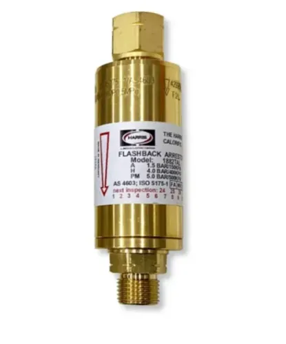
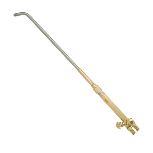
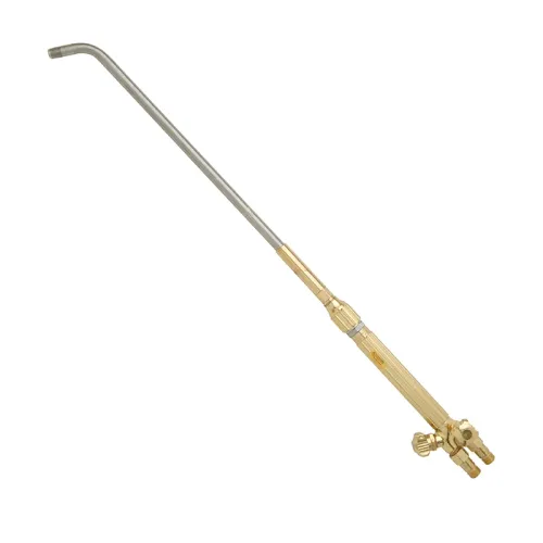
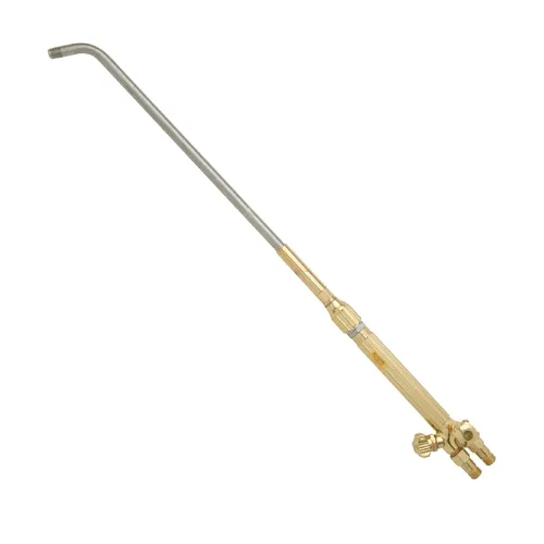
The Harris Gas Saver Model 653 is an in-line device that manages the initial shielding-gas surge when a welding machine opens its solenoid valve. A conventional regulator can release a brief high-flow burst into the hose; the Model 653 limits that waste before normal flow reaches the torch.
Its position in a typical gas line is:
- Cylinder to regulator or flowmeter: the regulator reduces cylinder pressure and sets the available flow.
- Regulator outlet to Model 653 inlet: connect the saver in the gas direction marked by the manufacturer.
- Model 653 outlet to the machine gas inlet: the machine’s solenoid valve then controls gas delivery to the MIG gun or TIG torch.
Place the saver upstream of the machine or torch gas-control valve. Installing it after the solenoid leaves the upstream hose volume exposed to the same opening surge, so it cannot address the waste it was selected to control.
The Model 653 is a shielding gas saver, not a replacement for the regulator, flowmeter or solenoid. It does not compensate for excessive flow settings, leaks or a restricted hose. Set the required flow for weld protection; the saver reduces the short burst during starts rather than shutting off gas during idle periods.
This arrangement supports MIG welding gas control and TIG welding gas control when the gas, fittings and pressure ratings match. In brazing, it can control inert purge or shielding-gas consumption, but it is not a fuel-gas regulator, flashback arrestor or flame-adjustment device.
Match the Gas, Connections and Capacity Before You Buy
Gas saver compatibility depends on the gas, pressure, flow range and fittings—not the regulator’s appearance. Confirm each item against the Model 653 data sheet and the markings on your equipment.
1. Identify the gas service. Use a regulator and Model 653 approved for argon or argon-CO2 shielding gas. Do not connect an argon setup to oxygen, acetylene, LPG or another fuel gas unless the exact device is rated for that service.
2. Match the regulator fitting. Check the regulator outlet size, thread type and connection standard against the argon regulator connection on the 653. Do not force an adapter onto a mismatched thread or combine fittings with different pressure ratings.
3. Check direction and placement. The regulator connects to the 653 inlet, and the outlet runs toward the welding machine or torch gas valve. Confirm the arrow on the body and record the inlet outlet connection before installing it upstream of the machine solenoid.
4. Compare capacity. Verify the 653’s allowable inlet pressure and flow range against your regulator setting, machine demand and torch requirement. An undersized hose, blocked diffuser or long restrictive hose can leave flow unstable even when the saver is correctly rated.
5. Map every connection from cylinder to torch. Include regulator, 653, hose, quick-connects, solenoid, machine, torch and hose bore. For brazing, confirm the setup uses compatible inert gas; the 653 does not replace a fuel-gas regulator or flashback protection. Reject the purchase if any fitting, pressure rating or gas approval remains unknown.
Install, Leak-Test and Operate the Gas Saver Correctly
Put the Model 653 between the regulator outlet and the welding machine’s or torch’s gas-control valve; placing it after the solenoid leaves the startup surge unmanaged. Confirm the arrow or inlet-outlet markings before making the Model 653 installation.
1. Close the cylinder valve, release pressure from the line, and fit the regulator to the correct shielding-gas cylinder. Complete the welding regulator setup with the regulator outlet facing the Model 653 inlet.
2. Connect the regulator to the Model 653 with the specified fitting and connect its outlet to the machine or torch gas valve. Keep gas hose routing short, supported, and free from sharp bends, hot surfaces, spatter, and crushing points.
3. Tighten every cylinder connection, regulator fitting, hose end, quick-connect, solenoid connection, and torch connection. Keep the machine valve closed while checking the system.
4. Open the cylinder valve slowly, set the regulator pressure, and perform a shielding gas leak test with an approved leak-detection solution. Bubbles indicate a leak: close the cylinder, depressurise safely, repair it, and test again.
5. Set the machine’s gas flow and trigger the valve while checking for a steady delivery. Do not treat the Model 653 as a flow-rate correction; excessive settings still waste gas.
6. For shutdown, close the cylinder, close the machine or torch valve, and release trapped line pressure according to the equipment procedure. Reopen the cylinder slowly during the next start.
Use the 653 for compatible inert-gas brazing arrangements only. It does not replace a fuel-gas regulator, flashback arrestor, ventilation, or flame-control practice.
Set Flow for Weld Quality, Not for Maximum Cylinder Life
Set the shielding gas flow rate from the weld procedure, nozzle size, joint geometry and surrounding air movement—not from a target for maximum cylinder life. Too little flow allows atmospheric contamination and weld porosity.
Too much flow creates gas flow turbulence that can draw room air into the shield, so the Model 653 cannot fix an excessive setting.
Set and troubleshoot in this order:
- Open the torch gas valve or trigger and set the flowmeter to the procedure’s starting value while gas is flowing.
- Check the nozzle, diffuser and torch angle; spatter, blockage or poor positioning can disrupt coverage.
- Remove drafts from fans, doors and compressed-air lines before increasing flow.
- Leak-test the hose, fittings and torch if the reading falls, the cylinder empties unusually fast or porosity continues.
- Increase flow only after these checks, then confirm the bead and porosity result.
For brazing gas control, the 653 affects only purge or shielding-gas consumption when the brazing equipment uses a compatible inert-gas supply and controlled valve or regulator arrangement. It does not replace the fuel-gas regulator, flashback protection or flame-adjustment practice required for oxyfuel brazing.
Do not connect an argon-configured regulator or Model 653 to oxygen, LPG, acetylene or another service unless that exact configuration is approved for the gas, fittings, materials and pressure.
Prove the Saving with a Before-and-After Measurement
A cylinder pressure gauge is a poor gas consumption measurement because pressure changes with temperature and does not show small withdrawals accurately. Weigh the cylinder instead, using the same scale and recording tare weight, gas type, date, machine settings and operating hours.
1. Run a baseline without the Model 653. Record the cylinder weight before and after a defined batch of welds, the number of arc starts, actual welding duty cycle, flow-meter setting and idle time. Repeat the measurement across at least three comparable shifts.
2. Install the Model 653 in the specified position, leak-test every connection, and repeat the same work. Keep wire size, material, torch, nozzle, flow rate, operator and start-stop pattern unchanged. For brazing, use the same torch cycle, joint count and heating time.
3. Calculate consumption as kilograms of gas used per weld, joint, arc-start or operating hour. Compare the baseline average with the Model 653 average rather than comparing two cylinders with different fill levels. This gas saver comparison exposes whether repeated starts, not the normal flow rate, caused the waste.
4. Check weld quality and shielding before accepting a lower figure. Excessive flow, a blocked diffuser, regulator creep, a failing solenoid or a leak can distort the result. Fix those faults and test again.
Multiply the gas saved by your delivered gas cost, then compare the monthly saving with the Model 653 installation cost and testing time. Rahul Industrial Products can help verify the regulator outlet, hose size and gas service before a mismatched connection invalidates the comparison.
Frequently asked questions
How does the Harris Model 653 reduce shielding-gas waste?
It limits the brief high-flow surge released when the welding machine opens its solenoid valve, then allows normal torch flow.
What should you check before buying a Model 653?
Confirm the shielding-gas type, inlet and outlet connections, pressure range, flow capacity and compatibility with your welding or brazing setup.
How do you install and leak-test the Model 653?
Install it in the gas line in the correct flow direction, tighten compatible fittings, pressurise the system and check every joint with leak-detection solution before use.
How should you set shielding-gas flow after installation?
Adjust flow until the weld has stable coverage without turbulence, using the torch, nozzle, gas type and job conditions as the basis rather than chasing the lowest setting.
How can you verify gas savings?
Record cylinder pressure or gas consumption over comparable work before installation, repeat the measurement afterward and compare jobs with similar arc time and flow settings.