A Model 601 marking alone does not identify a complete regulator specification. Before ordering, you need to match the exact gas version, connections, pressure ranges, gauge scales and flow capacity to the cylinder and process so that the regulator is safe, controllable and not undersized.
Key takeaways
- Match the full Model 601 number and nameplate to your exact gas service.
- Confirm inlet, outlet and cylinder connections before ordering; avoid improvised adapters.
- Choose pressure range, stage design and gauges for the process pressure and flow.
- Check flow demand, relief protection and freezing risk during continuous gas use.
Does the Exact Model 601 Variant Match Your Gas Service?
“Model 601” alone is not enough to select or replace a regulator. Harris Model 601 gas compatibility depends on the full model number and nameplate, because oxygen, acetylene, LPG, nitrogen, argon, carbon dioxide and specialty-gas versions can differ in connections, materials and relief arrangements.
A brass body proves nothing; brass can look identical across incompatible services.
Verify these details against the cylinder valve and process specification:
- Full model number, catalogue number and gas designation
- Inlet and outlet connection codes, including thread standard and hose connection
- Delivery-pressure range and gauge units: psi, bar, kPa or kgf/cm²
- Relief configuration and marked maximum inlet pressure
- Diaphragm, seat and seal materials for corrosive, reactive, wet or sulfur-containing gas
For oxygen, require documentation identifying an oxygen-compatible regulator and an oxygen-clean regulator. Oil, grease, petroleum lubricants, dirty gloves and contaminated hoses can ignite in high-pressure oxygen; do not infer oxygen service from a clean-looking finish. For acetylene, confirm the gas marking and the acetylene regulator pressure limit 15 psig under OSHA rules.
A high-pressure inert-gas regulator is not automatically an acetylene regulator. Check material compatibility for ammonia, chlorine and sulfur-containing gases before approving a general-purpose variant. If a quotation says only “601,” stop and request the complete specification in writing.
Do the Inlet, Outlet and Cylinder Connections Fit Without an Adapter?
Confirm four separate interfaces before ordering: the cylinder valve, Model 601 inlet connection, Model 601 outlet connection and hose connection. A regulator that screws onto the cylinder can still fail to connect to the hose or downstream equipment.
| Interface | What to compare | What failure prevents |
|---|---|---|
| CGA cylinder connection | Gas service, valve standard, connection code and gender | A mismatched valve connection will not seat safely |
| Model 601 inlet connection | Marked CGA code and regulator thread standard | Thread size alone can identify the wrong gas service |
| Model 601 outlet connection | Outlet size, thread, gender and pressure rating | The hose or equipment fitting may not seal or may be overpressurised |
| Hose connection | Hose-end fitting and downstream equipment fitting | An adapter can defeat the intended gas-specific connection control |
CGA cylinder connection is selected by gas service and the cylinder-valve outlet standard, not thread size alone. Compare the markings on the regulator with the installed valve, hose and equipment. Never force mismatched threads or use an unapproved adapter to defeat a gas-specific cross-connection control.
Check these details on the complete model number and nameplate:
- Inlet connection code and gas designation
- Outlet connection size, gender and thread standard
- Hose-end fitting and downstream equipment fitting
- Maximum inlet pressure for that exact suffix
Many configurations are listed up to approximately 3,000 psig, but that figure does not apply automatically to every 601. Keep the cylinder’s pressure at its highest expected filling temperature within the regulator’s marked maximum inlet pressure. A quotation stating only “601” is insufficient.
Are the Pressure Range, Stage Design and Gauges Suitable for the Process?
Match the delivery-pressure range to the actual operating setpoint, not to the cylinder pressure. A 0–200 psig regulator gauge gives poor adjustment resolution for a process running at 10–20 psig; choose a lower range when it covers the required setpoint and flow. For reference, 1 bar equals 100 kPa, 14.5 psi, or about 1.02 kgf/cm².
Keep the process and gauge units consistent.
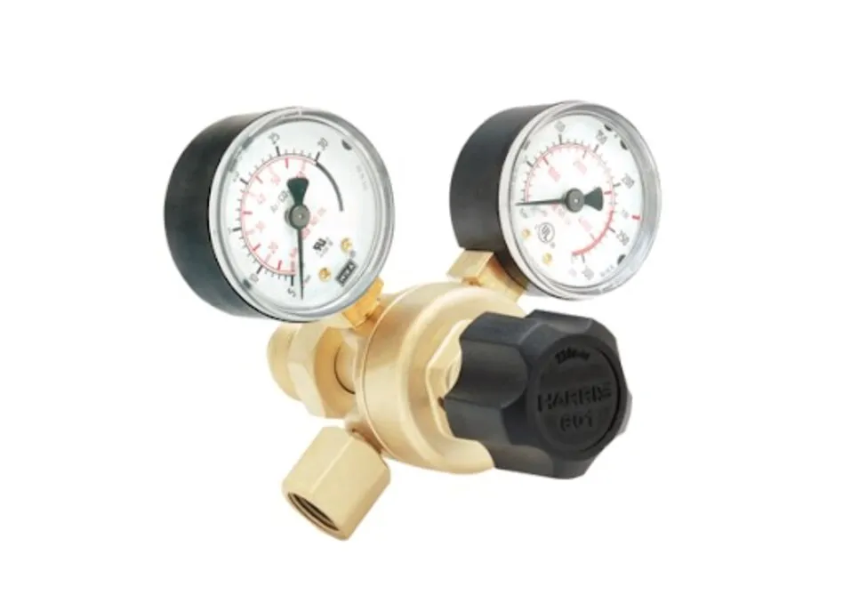
The Harris Model 601 single-stage regulator responds more to falling cylinder pressure than a two-stage regulator. That change can disturb paint atomization, abrasive blasting or welding. Use a two-stage regulator for better two-stage regulator pressure stability, or add a downstream line regulator when the 601’s available range and flow are otherwise suitable.
| Option | Pressure behaviour | When it applies |
|---|---|---|
| Model 601 single-stage regulator | Outlet pressure changes more as cylinder pressure falls | General service where that variation is acceptable |
| Two-stage regulator | Holds delivery pressure steadier through cylinder depletion | Sensitive spray, blasting or welding processes |
| 601 with downstream line regulator | Adds local pressure control near the equipment | Long lines or processes needing a stable final setpoint |
Treat the regulator gauge scale as a separate selection. A one-gauge version normally shows inlet, or cylinder, pressure; a two-gauge version adds outlet, or regulated, pressure. The contents gauge estimates pressure, not remaining gas mass precisely, because temperature and gas compressibility change the reading.
A regulator is not a flowmeter: use a correctly sized flowmeter or mass-flow controller when flow itself is specified.
Can the 601 Deliver the Required Flow Without Freezing or Overpressurising Equipment?
The selected 601 configuration can support welding, cutting, heating, purging, laboratory or process-gas work only when its rated flow matches the actual duty. Treating it as a universal flow-control device can cause pressure loss, icing or equipment damage.
1. Separate intermittent peak flow from continuous flow. A cutting demand lasting seconds is not equivalent to continuous carbon dioxide, shielding-gas, purge, blasting or spray demand.
2. Check the applicable flow curve or test condition for the exact configuration. Model 601 flow capacity depends on inlet pressure, outlet pressure, allowable pressure drop, gas molecular weight and manufacturer-specified droop. Do not accept a catalogue maximum as available flow at your required outlet pressure.
3. Calculate the actual regulator pressure drop and watch continuous demand. High-throughput carbon dioxide can cool the regulator through expansion; carbon dioxide regulator freezing can produce icing, unstable delivery or seat malfunction. Similar effects can occur with other gases at high flow through an undersized body.
4. Use the 601 to supply pressure, not to measure flow. Add a correctly sized industrial gas flowmeter, mass-flow controller or downstream valve when the process specifies a purge, shielding, blasting or spray rate.
5. Protect downstream equipment independently. A built-in relief valve does not replace overpressure protection for the weakest hose, spray tool, welding system or blasting control. Size external protection for seat failure, blocked-in thermal expansion and incorrect adjustment.
What Should You Put on the Purchase and Installation Checklist?
Record the complete configuration before you buy: “Model 601” alone is not a specification. Use this Model 601 procurement checklist and require the seller to confirm every field in writing, rather than accepting a quotation that says only “601.”
- Exact Model 601 suffix and nameplate marking
- Gas designation, including oxygen, acetylene, LPG, nitrogen, argon or carbon dioxide
- Maximum inlet-pressure rating, checked against cylinder pressure at its highest expected filling temperature
- Delivery-pressure range and required continuous and peak flow
- Inlet and outlet connection codes, thread standard, gender and sizes
- Inlet and outlet gauge full-scale values, with units such as psi, bar or kPa
- Relief arrangement and set pressure
- Downstream component’s maximum allowable pressure
Rahul Industrial Products can help compare the marked regulator variant with the cylinder valve, hose and process equipment; that verification service does not replace your engineering checks.
| Check | Confirm before approval | Reject or investigate if |
|---|---|---|
| Flow | Applicable flow curve, gas and test condition | Only a catalogue maximum is quoted |
| Gauge | Full scale suits cylinder and operating pressure | Scale is too broad for useful adjustment |
| Protection | Relief and downstream pressure limits | The weakest hose or tool is unprotected |
For installation, secure the cylinder upright, clean the valve outlet and regulator inlet, back out the adjustment screw, then open the cylinder valve slowly. Perform the industrial gas regulator leak test with an approved solution or detector. Never use a flame, and never apply ordinary petroleum lubricants to oxygen equipment.
Frequently asked questions
How do you match a Harris Model 601 variant to the gas service?
Read the full model number and nameplate, then confirm that the regulator is designated for your gas, such as oxygen, acetylene, LPG, nitrogen, argon or carbon dioxide. Check connections, materials and relief arrangements before replacement.
What connections should you check before buying a Model 601?
Compare the regulator’s inlet, outlet and cylinder connections with the cylinder valve, hose or pipework and downstream equipment. Confirm thread type, size, gender and connection standard so you do not need an adapter.
How do pressure range, stage design and gauges affect selection?
Select a pressure range that covers the required inlet and delivery pressures without operating at the edge of the adjustment scale. Match single-stage or two-stage regulation and gauge scales to the process.
How can you check whether the 601 will deliver the required gas flow?
Compare the regulator’s rated flow at your inlet pressure, outlet pressure and gas type with the process demand. Check continuous-use conditions for pressure drop, freezing risk and downstream overpressure protection.